1. What should I do when the fuel dispenser can not be started up or can be started up intermittently?
A1: fuel dispenser is provided with a startup time-lag function that requires that the waiting time from nozzle hanging shutdown to a next nozzle lifting startup must be greater than 3 seconds. After nozzle hanging shutdown, please wait for 3 seconds, and then conduct nozzle lifting startup.
A2: Nozzle switch works abnormally, please maintain or replace the nozzle switch.
A3: Control board works abnormally, please maintain or replace the control board.
A4: Mainboard works abnormally, please maintain or replace the mainboard.
A5: AC contactor cannot be picked up or can be picked up intermittently, please maintain or replace the AC contactor.
A6: Power supply is abnormal, please check the power supply.
2. Faults that leading to fuel dispensers can’t give out oil and solutions
Faults that leading to fuel dispensers can’t give out oil and solutions
(1) Fault:motor dosen’t work
Solution: Check the line, switch, fuse, relays, motors, etc.
(2) Fault: V-belt of the motor is too loose, rotated speed of the oil pump is insufficient
Solution:Adjust the belt tension or replace the v belt.
(3)Fault: Oil in the tank is not enough or the tank is empty.
Solution: Fill oil in the tank.
(4) Fault:Quality of the oil is not good
Solution: Replace with qualified oil.
(5) Fault: Bottom valve is not working.
Solution: Check the valve face, repair or replace the bottom valve.
(6) Fault:There is leakage with the pipe which connects the tank and the fuel dispenser.
Solution:Check the sealing of relevant connectors and the valve parts.
(7) Fault:There are too much dirt in the filter.
Solution: Clean or replace the filter
(8) Fault:Vanes of the pump were stuck or broken
Solution: Clean or replace the vanes
(9)Fault:Vane pump is used for too long time, and the efficiency is poor.
Solution: Replace the vane
(10)Fault: Spring of overflow valve if broken
Solution:Replace the spring.
(11)Fault: Connection between the oil Inlet and pump suction port is not sealed.
Solution:Check if the shell is broken, add seal gasket and tighten the blot.
3. Working principle of self-sealing nozzle on the fuel dispenser
When refueling, the main valve is opened, the pressured oil will enter into the cavity between main and auxiliary valves inside the nozzle body and push through the auxiliary valve overcomes the force of spring, , then it will be discharged out of the nozzle. The auxiliary valve is used to prevent the liquid oil from flowing out of the cavity between main and auxiliary valves inside the nozzle when main valve is closed. If the main valve is not yet closed when fueling is over in process of preset refueling, the auxiliary valve may prevent oil in the nozzle and the static-conductive delivery hose from flowing out.
When oil passed through the auxiliary valve, the pressure inside the upper chamber in switching-membrane will be reduced . However, since the upper chamber in switching-membrane is open to the environment through an inclined hole in reducing sleeve, intake pipe, and the intake mouth of nozzle, external air may be supplied to the upper chamber in switching-membrane. So the pressure inside the upper chamber in switching-membrane may be kept equal to that inside the lower chamber (equal to atmospheric pressure), and the switching-membrane is maintained in its equilibrium position.
When the oil intake inside, negative pressure is established inside the upper chamber since it isolating from the ambient atmosphere. However, atmospheric pressure is still maintained inside the lower chamber; thus, a pressure difference ΔP appears between the upper and lower chambers. When ΔP is reach a certain value, the switching membrane haunches up and move the fitted self-sealing stem upward.
The steel ball is pushed and drops into self-control stem hole. Under the action of pulling force of switching handgrip, the self-control stem moves downward. The ejector pin of main valve moves downward since the pivot-point of switching handgrip move down. The main valve is closed, then with the stop of oil supply (in other words, the nozzle is self-sealed).
4. What is the function of an oil/gas separator for a fuel dispensing system
An oil/gas separator is a pressure vessel used for separating well fluids produced from oil and gas wells into gaseous and liquid components.
There are more or less air in the underground tank. When fuel dispenser dispensing oil from the tank, some air may brought into the fuel dispenser, which may cause the the metering system not accurate. By the oil/gas separator in the pumping unit, the air will be reduced maximally to grantee the accuracy of the whole unit.
The separation working principle could be briefly described below.
The end cap of oil-gas separator may channelize the flow and increase the flow rate. When oil flows from the pump outlet to the separator, the sectional area gets smaller and smaller, and the flow rate gets higher and higher. Under the action of flow channelizing arc of end cap of the oil-gas separator, liquid oil flows forward spirally down the inner wall of separator. The gas density and centrifugal force is low, and oil and gas are separated; the gasses are gradually built in the center, and the gas-oil mixture is discharged into the oil return chamber through the vent-pipe subassembly. When the liquid oil is built up inside the oil return chamber to a certain extent, the floater floats upward due to the effect of the buoyancy force and drives the valve core to move up, the float valve is opened, and the liquid oil flows back to the pump intake.

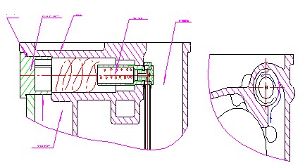
Functional diagram of oil and gas separator
5. Working principle of fm-500 flow meter for SANKI fuel dispenser
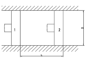
Currently, all flow meters of fuel dispensers fulfill metering by reciprocating motion of its piston. As shown in Fig. 7.3.2.1, under the action of high-pressure fuel, the piston travels a distance L from position 1 to position 2, and discharge a certain volume of fuel. On the assumption that the cylinder bore of flow meter is D, volume of the metered fuel may be " ![]() ".
".

Fig. 7.3.2.1 Functional diagram of flow meter FM-500
We may analyze the above-mentioned equation, and find out that cylinder bore D of flow meter is a fixed value that may not vary during operation; major factors that may influence the metering accuracy and repeatability accuracy of flow meter are travel stroke L of the piston and the sealability of flow meter.
Two (2) types of motion mechanism are available for flow meters, i.e. crank arm type and cam type. The 2 types have their own merits and demerits, and there are no essential differences between them. To facilitate the analysis, crank mechanism will be taken as an example in the following. Both crank mechanism and cam mechanism may convert translational motion of piston into rotary motion of output shaft, and the two have their own dead center positions as well. In order to ensure the whole flow meter to run normally and pass through the dead positions successfully, multiple pistons (4 pistons in most cases) are usually adopted to drive the output shaft jointly.
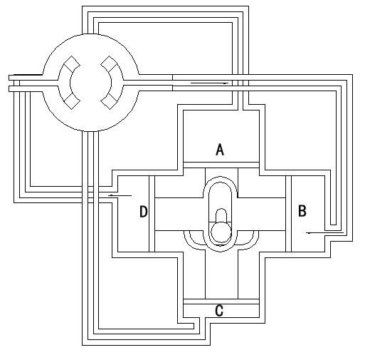
Since flow meters are equipped with multiple pistons to work jointly, the flow meter needs a control command center to control the motion of the pistons such that the motions of the pistons may be coordinated properly. The control command center is exactly a distribution valve. A functional diagram of common flow meter is shown in Fig. 7.3.2.2.
.jpg)
Fig. 7.3.2.2 Schematic diagram of flow meter
When high pressure fuel is distributed by the distributing valve, via fuel pipes, it respectively enters into cavities A and B, while cavities C and D are connected to the outlet of the flow meter via fuel pipes and the distributing valve. Under the action of high-pressure fuel, piston group AC traves from A-end to C-end, and piston group BD travels from B-end to D-end. In the mean time, the two piston sets jointly push the crank to rotate clockwise, and the distributing valve rotates clockwise as well.

Fig. 7.3.2.3 Functional diagram of flow meter FM-500
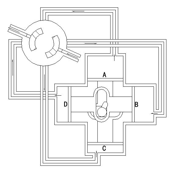
When the flow meter moves to the position shown in Figure 7.3.2.4, the distributing valve closes all the inlet and outlet fuel circuits of piston set AC, so piston set AC is at the dead position. Then, piston set BD continues to move from end B to end D, and pushes the crank to continue to rotate. Pushed by piston set BD, the distributing valve reopens the inlet and outlet fuel circuits of piston set AC, it is just that the inlet and outlet fuel circuits are switched, which enables piston set AC to cross the dead position, its moving direction is changed to moving from end C to end A, i.e. piston set AC realizes direction switching, as shown in Figure 7.3.2.4.

Fig. 7.3.2.4 Functional diagram of flow meter FM-500
And so forth, under the effect of high pressure fuel, and controlled by the distributing valve, the flow meter works in a coordinated way. This is the whole working principle of the flow meter.
6. What is the function of a bypass valve of gear pump in the dispenser?
Bypass valve is a parts of the gear pump in the fuel dispenser. It is mainly used to limit the maximal pressure of hydraulic system and protect it from damage by the high pressure.It also could adjust flow rate of the fuel dispenser.Bypass valve is important in the hydraulic system through which oil is pumped to maintain an even pressure and keep the system operating.It is crucial mechanisms for controlling the flow and pressure of liquids.
The bypass valve is triggered by a springloaded mechanism that opens when fluid pressure becomes too high or too low. As long as the pressure is the same on both the inlet and the outlet side of the spring, the switch remains closed. But if the pressure builds up too much on one side, the spring is compressed, causing the switch to open. Without bypass valve, the pump may be still running , the oil could create too much pressure with nowhere to flow out, leading to a stalled engineor an explosion. But before that happens, the bypass valve opens to vent the pressure and divert the oil back to the pump’s reservoir.


